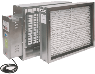
Installer’s Guide

The CosaClean arrives in one or two shipping boxes. One box contains the filter chassis, and filter. The second box contains the CosaClean Air Purification System. (Depending on the customer’s configuration the filter chassis and filter may not be required).

Step 1. Unpacking the Product(s).
Take appropriate care unpacking and handling the equipment, there may be sharp edges. Observe and inspect the product while unpacking.
Step 2. To install the product into the HVAC system
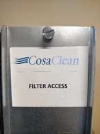
To install the CosaClean into the HVAC system it may be necessary to access the inside of the product – to fasten to existing duct or air handler. Remove the filter access door by unscrewing the fastener at the top and bottom (shown in image 1) of the door. (Note both sections have bendable tabs for easy attachment).

Image 1: Remove the filter access door by unscrewing the fasteners.
Step 3: Remove the filter
Slide the filter out buy gripping the cardboard surround lightly on either side and pull the filter out in a straight motion. Set the filter to one side.

Image 2: Remove the filter and set aside

Step 4: Determine Return Air Flow Direction.
The product is installed in the return air path of the HVAC system. The product fits a standard rectangular plenum 21” X 25” (54.34cm X 63.5cm) and requires 11” (28cm) of space. Figure 3, below, shows the dimensions, air flow and component parts of the product.

To determine airflow direction in the return air path, set the fan to ON and open the access door to the filter and remove the filter from the existing air handler (The CosaClean includes a 2” pleated filter, with minimum rating of MERV 8). If the air flow direction is not obvious, hold a piece of paper in where the filter was previously housed and note the direction it is bending. This determines how the product will be configured in step 4.

Figure 3.  CosaClean showing return air flow direction, dimensions and system components

NOTE: The filter should ALWAYS be the FIRST item the return air passes through.

 Once you have determined the correct orientation for the product move on to Step 5.

Figure 4a and 4b below show the correct position for the product in both vertical 4a and horizontal 4b configurations.
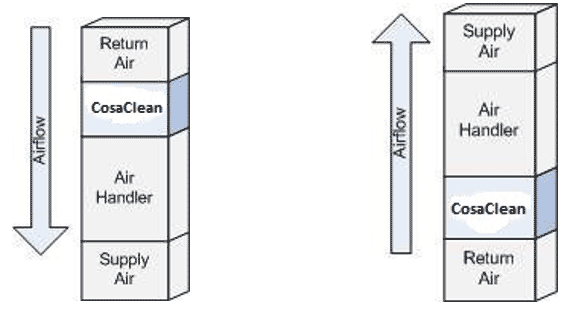
Figure 4a. Vertical airflow configuration

Figure 4b. Horizontal airflow configuration

Step 5. Configure the Product
By inverting the chassis this will allow you to install the unit with the filter chassis to the left or the right and facing the direction you need to provide sufficient filter access.

Figure 5. Allow for a minimum of 30” in front of the installed unit to remove and replace the filter during routine maintenance.

Step 6. Determine filter accessibility.
It is necessary to replace the 2” pleated filter approximately twice per year depending on the air quality inside the home. It is therefore important that the homeowner has easy access to the filter and operation lights of the system. Figure 5. Shows the amount of clearance required to access the filter on the unit.

DO NOT replace any of the components until the chassis is installed in the duct.

Step 7. Opening the Duct to Accommodate
You will need to provide an 11” (28cm) space in the return air duct to install the unit. This is typically easiest at the air handler. Remove the duct tape and sheet metal screws that fasten the return air duct to the air handler. If you have a circular return air duct, it may be necessary to install a duct adapter to accommodate the product. Remove or separate the return air duct to provide 11” space.
Step 8. Support the Chassis.
Provide adequate support for the product which weighs 35Lbs (15.88Kg). The chassis can either be supported underneath or suspended from a ceiling joist or other mounting area. Be sure to have the unit supported evenly so it is sitting square.
Step 9: Fasten to the Existing Duct.
Using self-tapping sheet metal screws fasten the product to the existing duct and air handler on the inside of the chassis using the turned-in flange as shown in image 5 below.
Step 10: Reinstall the Filter
Carefully slide the 2” pleated filter back into the unit using the filter slide track shown in Image below.

Use sheet metal screws to fasten the CosaClean chassis to existing duct and air handler.

Note: Tape the joint to eliminate leakage

Carefully slide the 2” pleated filter back into the unit using the slide track.

Note: If airflow direction is not indicated on the filter, the wire side of the filter should be facing the grids i.e. facing the return air stream.

Step 11: Reinstall Filter Access Door
Insert the two door fasteners into the holes at the top and bottom (left and right for horizontal installations) of the door access holes. The door should fit snuggly against the insulation with no air gaps.
Step 12: Connect Unit to Power
The CosaClean is delivered with a 6’ (1.8m) captive cord with a three-pin molded power connector. Plug the connector into a non- switched 110V grounded outlet. DO NOT REMOVE MOLDED CONNECTOR AND HARD WIRE.

The CosaClean unit must be wired to a dedicated uninterruptable circuit.

Check that the product is working by verifying that the two green High Voltage and High Frequency LEDs are illuminated on the front of the CosaClean system. As shown in image below.

Verify the two green LEDs are illuminated once connected to power.

For General Inquiries:

Email